
The Importance of Quality Infrastructure in Lab Facility Design: Part 2
By: Scott Paden (Harvey | Harvey- Cleary), Skye Smith (Kirksey Architecture), and Tanvi Solanki (Kirksey Architecture)
As laboratory facilities become more complex, it has become important to consider both industry trends and their impact on lab personnel when dealing with infrastructure. Longevity, quality of equipment, abundant capacities, and accessibility have long been thought to be considerations when defining quality infrastructure. The definition, however, of quality infrastructure for laboratories has changed in recent years, becoming somewhat synonymous with future flexibility. Although the concepts of quality infrastructure and future flexibility may be intertwined, the former encompasses more than the idea of providing spare circuits or excess cooling capacity for Day Two needs. It considers smart planning ideas like the scalability of systems, “isolatability,” adaptable interfaces, and “obvious” accessibility while focusing on safety and operability for the facility users. When accounted for and implemented according to the project in question, these strategies can optimize and future-proof the building.
In Part 1, smart planning strategies for quality infrastructure were defined. The two key remaining ideas of incorporating adaptable interfaces and “obvious” accessibility for elements are discussed subsequently.
Adaptable Interfaces
The infrastructure of the facility should have adaptable interfaces to modify components to an isolated portion while keeping the rest of the building functional. Every lab module should have the ability to connect to additional mechanical, electrical, and plumbing services as demands change because accessing capacity in the long term is harder than providing capacity on Day One.
Utilize the Roof. The roof is another floor of a lab building – this area plus your plant are the two biggest maintenance areas. Getting personnel and maintenance materials to the roof is inevitable and necessary, and it affects space planning below. With the high-cost point of research facilities, clients may elect to move away from utilizing a structured penthouse and decide to use the roof to place air handling equipment. Although providing roof access with stairs is preferable over an access hatch, stairs require more space and can be costlier. Adding a material lift instead can provide the safest means of getting bulky and heavy materials to the serviceable areas and, in turn, can encourage regular maintenance.
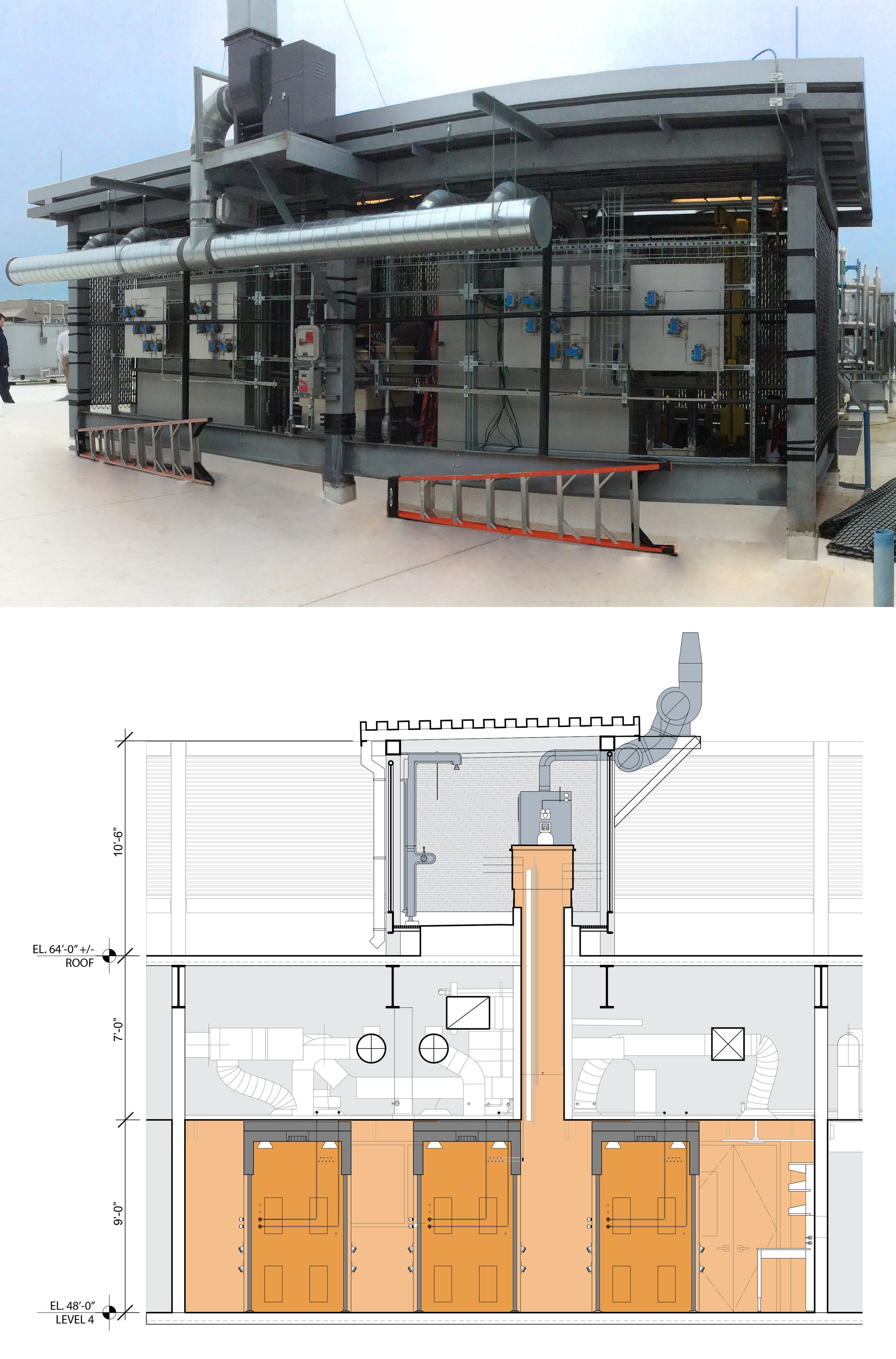
Sometimes, supporting research can put operators in areas that may not be typically used. In the example above, the gases being used in the project necessitated a direct welded connection from the cylinder to the area of research. A portion of the roof was then designated as a secured outside storage area to accommodate this need. Additional studies on pallet jack maneuverability and equipment support were executed to ensure that the roof could be used for this purpose. Furthermore, the roof was templated with the same floor load capacity as a typical building level to allow it to be used for a variety of reasons within code limitations. Without the foresight and planning, the roof may not have been as highly serviceable as desired.
(Kirksey Architecture)
Process Loads. Loads are almost always additional, and most of those are comprised of process loads for research equipment. Often, newer technologies for research equipment start off at their highest draw on power and other utilities; as time passes, technology improves and new equipment becomes more efficient, allowing flexibility for the facility. When accommodating new process equipment loads, striking the right balance between cost, maintenance, service, and energy usage goals is key.
In addition to providing an electrical panel per lab module to allow for isolation, consider upsizing the number of circuits in each panel. Very often, a piece of equipment in a lab is moved or replaced, and the old circuit is abandoned in place while a new one is added. Rather than oversizing the energy intensity of the lab (by increasing watts per square foot), increase the number of circuits beyond what is needed for the anticipated lab function. This way, the lab has the capacity to lend itself to future functions.
Process Cooling. Even if the client does not request additional process cooling for Day One, plan for the long-term possibility. Process loads must deal with heat rejections, and the most economical way to handle this is to provide an array of floor drains in the service corridor to allow for future chiller additions.

If the requirements of future equipment cannot be identified on Day One, consider how existing utilities can be maximized for Day Two needs. This example depicts a prefabricated process chilled water station that stemmed from the main chilled water loop. These stations were user-calibrated for flow and temperature, providing for near-unlimited variability in future equipment needs. It was also a cost-effective solution to provide for process cooling without adding miles of pipe on Day One.
(Kirksey Architecture, Aker Imaging)
Change and Life Safety. The code is safe, but it doesn’t dictate operability. The architect or lab planner needs to think beyond what is prescribed in the code and lead the process for discussions on interface, locations, and heights of infrastructure. Consider the placement of fire-rated assemblies and how they separate control zones in a laboratory. If possible, avoid fire-rated assemblies between the service corridor and lab as well as from the mechanical plant to the service corridor. Such considerations can allow the user to make modifications without it becoming a burdensome undertaking.

One thing in particular to consider is the pressure differentials in lab spaces, in which the laboratory is usually the most negative relative to its surroundings. Often walls are tightly sealed in laboratories to fine-tune the pressure differentials that need to be tracked. In this example, the engineer designed the pressure cascade to allow for a total CFM per lab module to include the planned openings between the labs and the service corridor. This created the opportunity for lab users to make regular modifications to the research spaces.
(Kirksey Architecture/ Arup)
“Obvious” Accessibility
Traditionally, it has been acceptable for serviceable components to be accessible above a lay-in ceiling. This, however, can potentially require extensive on-site verification of various elements, especially if as-built drawings of the facility are not up to date. The idea of “obvious” accessibility resolves this issue by locating the serviceable components outside of walls and in plain sight. Utilities should be distributed in service racks and in ceiling openings organized in proximity to their respective controls and equipment. Of course, placing these serviceable elements at an accessible-height can enhance the user experience.
Plan the Pathway, not the Pipe. Since the needs of laboratories can change constantly, the goal is to plan for flexible pathways and not for the pipes themselves. Provide each lab module the opportunity to access connections for chilled water, sprinklers for gas cabinets, grounding, specialty power, and other unique utility conditions the client could potentially employ. Specialty power can be homeruned from the electrical room to the service corridor to allow the owner to bring 480v power to lab modules along the corridor path. For gases, provide a dedicated gas cabinet for each lab on Day One, as well as a path for specialty and house gases. The service corridor and the underside of the interstitial space can lend itself to a pipe rack. An exposed utility tray directing gases within the lab environment can further increase accessibility.
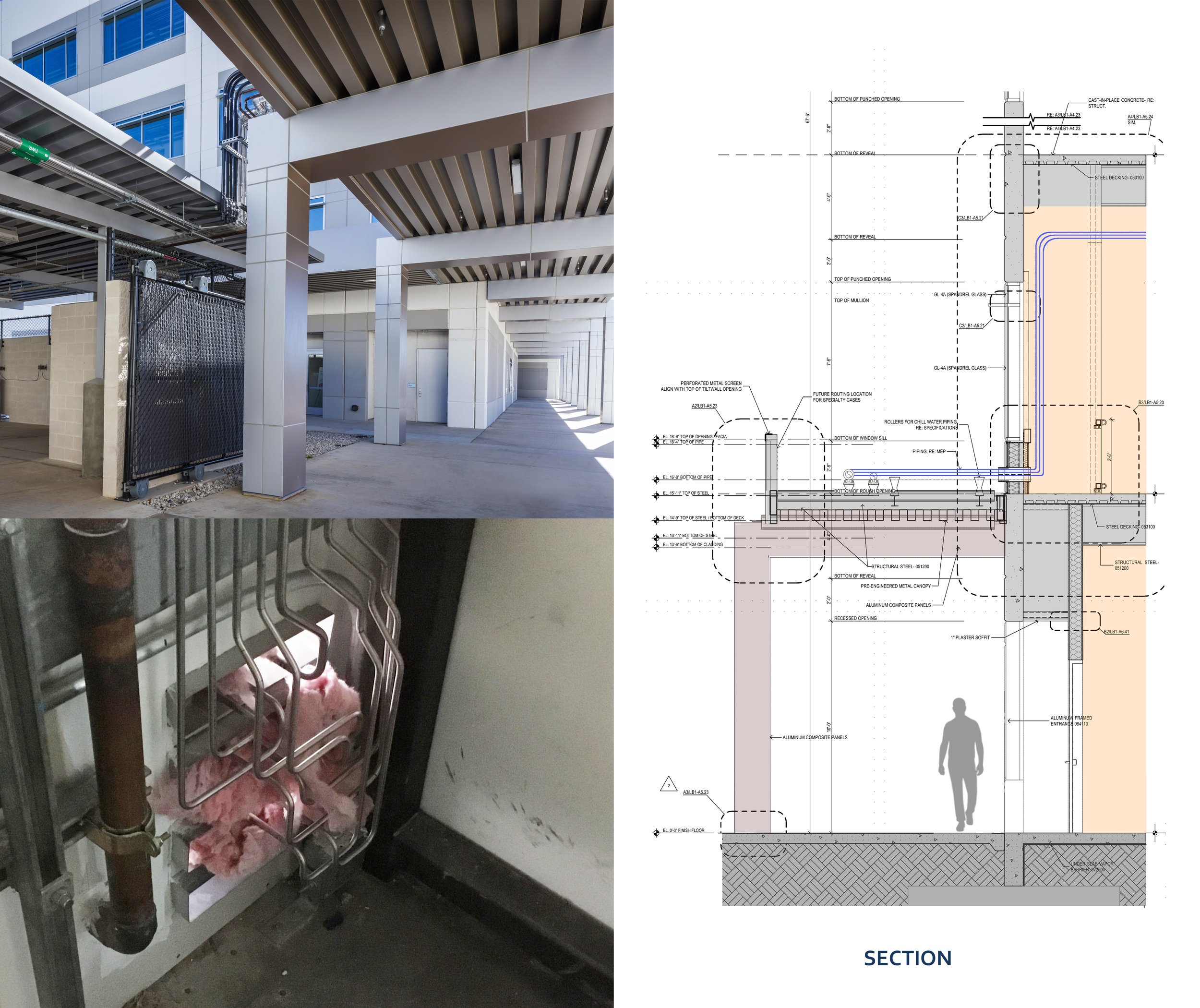
Sometimes a consensus cannot be reached on piping material, sizing, and needs. This campus project had multiple outside storage areas that distributed utilities to the labs with an exterior pipe rack. This planned pathway through the building opening provided empty racking that was modifiable.
Kirksey Architecture
Plan for Free Wall Space. It may not be clear upfront how many transformers, variable frequency drives, and other ancillary controls for equipment will be needed at the start of a project. But as facilities grow smarter, the need for such technology can only be predicted to increase. Often, specialty subcontractors are the ones who are tasked to place many of the interfacing devices that building engineers will interact with in the long term. Subcontractors are typically install according to code and what seems the most feasible to them at that moment, not necessarily taking into account the long-term maintenance and accessibility implications of those installed components. By creating regular zones of free wall space sprinkled throughout the building, those specialty vendors are now able to place those controls adjacent to the equipment it serve and within arm’s reach.
With the ever-evolving nature of laboratories, providing the ability to adapt to future conditions is crucial. Creating predictable patterns, pathways for accessibility, and nodes for capacity maximization are all highlights of smart planning strategies. Placing the users at the center of the design process not only facilitates planning decisions but can better ensure long-term usability and safety.
For the adjoining webinar, please visit https://www.labdesignnews.com/events/facilities-infrastructure-webinar-series.